Naming and Environment
Before you go further, title the design and describe it using the fields at the top of the page. These will be used in the summary along with a thumbnail in the design picker.
Environment and Default Locations
Each design as the notion of a single environment, such as production or development. Everything drawn in the canvas will belong to that domain and by separating implementation purpose into different designs, makes it easier to control reliability.
Along the top of the canvas is a text field in which can be typed the environment name, four boxes for default locations and also the catalogue model being used.
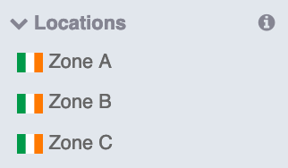
The image below shows a test environment label together with three locations in Ireland - zones A to C, denoting the availability zones in an Irish data centre.
For simple cloud deployments, it often doesn’t matter where the service will be located. The most convenient for users and the best price would be the default position.
However, when designs become more critical, geography often becomes a factor. Either to maintain resilience, to keep data close to users in a global context or to comply with legal jurisdictions. By explicitly modelling the location in the designs, it puts geography in the hands of the designer as a response to requirements.
Locations are specific to a catalogue, although there are some generic ones too (see later). Location labels are held in the top of the catalogue and can be dragged down with a mouse to the default location slots.
Tiers and Locations
All designs occur in tiers, representing sections of the design, which is similar to traditional approaches. Examples are database, compute, and web tiers. There can be any number and they will always be represented sequentially down the page. Tiers hold networks.
The tiers also locate the position of the design assets.
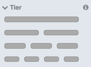
Different locations can be expressed in different tiers to give the most flexibility when a design needs to show a great diversity of venues. There is a limit of four locations across a page in a tier.
The System Garden diagramming standard represents locations as horizontal columns of components, linking in to the vertical groupings of tiers. This allows similar functional components to show a link across locations in a graphically logical way. For example, a database can show a replication path to its peer in another location in a simple way that aids rapid comprehension.
To avoid adding locations on each tier manually, use the defaults as shown above. Once locations are set, each tier will be allocated an initial location when it is dragged out on to the canvas. To remove location, hover over the location and click the red ‘X’. Then you can replace it with a suitable new location from the catalogue.
Tiers are generic and are dragged out from the top of the component list. Locations are specific to catalogues and should be dragged out in to the tier boxes. This assigns the components in that box to that location.
With the abstract catalogue, there are four locations (A, B, C, D) and a selection of countries in drag-out labels. But with cloud catalogues, the locations are physical and represent locations or availability zones of their data centres.
Networks
The next phase in building up a design is to add networks to each tier.
Clouds generally only have a single type of network. However, other infrastructure providers can provide several types of network, including an IP+SAN combination. For example, a 10 GB and 1 GB Ethernet may be offered and the design may want to use a specific type or even both.
Slide the chosen network into the tiers. The example below is a single tier with two locations.
The network component appears as an icon, a description and a name, with dropping regions above and below to place hosts and services.
Each network has a name (Default network in the oval label in the above example), and that is used to segregate traffic in a design. If every network has the same name, then the traffic is shared and every point can communication with every other point. This is the convention and unless you want a specific outcome, its generally best to leave it.
If there are different network names, they will be disconnected and the designer will have to connect them together with more components.
It is also convention that any design is a 'bubble' and isolated from any other design that may have been deployed with System Garden or manually. The design has its own Virtual Private Network. To connect to the outside world requires connectivity, which is covered later.
Hosts
The next most significant entity to build up is the host (or service, covered next).
The host is a set of processors, memory and storage that is able to run a stack of software and attach to a network. Hosts range in size and power from large physicals down to just enough cycles to run individual functions.
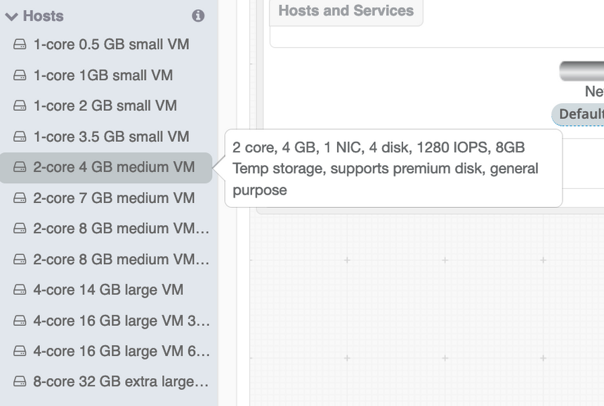
Hosts have their own category in the catalogue selection panel; below is an example. Hovering over the host label gives an expanded description of the device in question.
The network structures previously dropped into the tiers have two drop zones named Hosts and services. Anything dropped into the zone associates those components with that network. So, if a set of hosts need to be attached with a fast network but others can be slower, two different network types would be placed on the design and hosts placed accordingly. The faster network technology may be more expensive, so by utilising both, a cost saving may be gained.
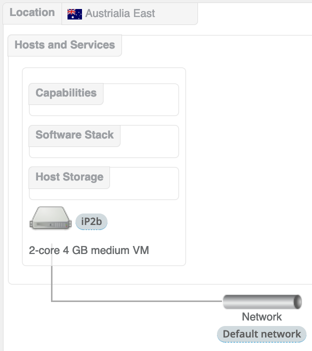
Dragging out a machine to the Hosts and services drop zone redraws the diagram like below.
By default, a network line is drawn from the component to the network device, which is to aid visualisation and it took like a network diagram. This can be used to make the diagram more readable or to emphasise aspects of the design.
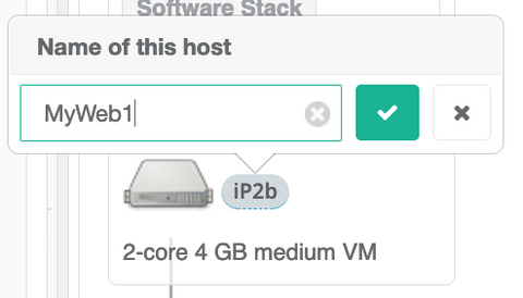
The representation of the host has an icon with its name to the side and a description below. In the example the name is iP2b as an automatically generated name, but this can be renamed to be more intelligible, although they do have to be unique and follow host naming conventions for your infrastructure provider.
Above the icon are a set of three boxes, each a drop zone for a different type of component: Host storage, Software stack, Capabilities. These are all filled by draggable items from the catalogue list and covered in more detail below.
Host Storage
The storage section of the catalogue list contains raw volumes that can be placed in various parts of a design that acct storage components.
Storage can be any non-volatile technology, such as NVMe or spinning disk. Within that are different capacities, capabilities and performance levels.
There are three types of storage:-
Host
Direct attach to a host, which may be genuinely local or appear local
Network Attach Storage (NAS)
The storage volume from a NAS service that can be attached to a host over an IP network. This typically models file storage
Storage Area Network (SAN)
Storage volume from a SAN device that can be attached to a host over a fibre channel or IP networking. Typically models block storage.
Storage persistence is dictated by the hosting provider. SAN and NAS storage as a remote method, is typically persistent across host transformations. Host storage will be lost when the host is destroyed unless the vendor supports on-going persistence with a flag. This will be available to select in the storage component configuration.
Software
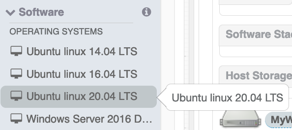
The software box holds a stack of software, which should have an operating system as its minimum, held at the base of the stack. Additional packages above the OS can be layered on and will be added in ascending order.
and following the list to layer software sequentially. This allows control of any side effect that may be caused of desired by the complete ensemble. Each item is a package method supported by the host type, typically Linux RPMs, DEB packages or Docker images.
Host Capabilities
An additional box attached to a host (not shown), allows us to associate a capability or a service to a specific host. For example, the allocation of an external or internet IP address or a storage back-up service that has host specific settings.


