System Garden builds designs from a catalogue of components.
There are many catalogues to chose from and each corresponds to a target infrastructure, cloud provider or abstraction.
In architecture terms, this is known as a Technical Reference Model (TRM).
This document describes the catalogue, how it works, how to make and maintain them.
Overview
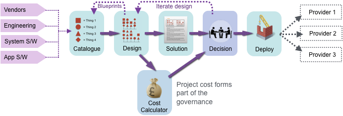
The following diagram shows a workflow between the tools that comprise System Garden .
Counter intuitively, we should start with the providers on the right. Each provider (1, 2, 3 in the diagram) represents organisations such as Amazon Web Services (AWS), Google Cloud Platform (GCP) or Microsoft Azure. Each will have a huge catalogue of products and services that can be rented on their infrastructure.
The provider catalogues are normally so large, that it can be quite perplexing which product to use, even for very experienced people. Ususally, an organisation that uses cloud will only accept a subset of products, so that fit with the overall use cases of that enterprise.
The arrows on the left of the diagram represent the engineering teams, architects and vendors that will have an input into the selction of the products and also how they are to be integrated into their existing estate. Typically several catalogues are created or imported into a Fabric instance and used to create designs. These design ultimately are used to deploy into the providers (skipping solution and design), where the component references and configurations reach their correct context.
As provider product lines change or the methods of deployment alter, then the Fabric catalogue will need to be adapted to track these changes. Potentially the designs will need updating also.
The catalogues and designs in System Garden also yield ad-hoc cost estimations based on capital and monthly operational costs, time to build and support life.
Catalogue Portability
Each catalogue has a unique identifier, which is referenced by the designs that use it. The defintions can be moved from system to system using a command line utility sgcat. Catalogues can also be propagated from a central point using RSS or atom feeds. Periodically, Fabric will poll the supply locations to see if any standard catalogues have been updated.
Abstract Catalogue, Generic Components
In addition to specific catalogues of technology, there is an abstract catalogue that contains a set of generic components. These are usful for createing an abstract design without referencing prodvider technology. It helps when creating a design in priciple before sizing a system or deciding the ultimate deployment.
To help in conversion from one catalogue to another, the core generic components are placed in every catalogue, without having to be specifically included. To convert, change the components into generics, then change the catalogue to the one desired, finally changing each generic to the desired vendor components.
Catalogue Component Types
The catalogue is a local database of around eight types of components; within some are further sub types. These are as follows:-
Location
Venues where computing takes place. These are named data centres or data halls (cloud people call these availability zones) and have its geographic location specified.
Network
Divided into four sub types, these are the technologies that connect equipment of participants together. The sub types are:-
1. Area connection - Mass connection of many machines into common peer communication with similar levels of access. Eg LAN or SAN
2. Control points - Technology that links two or more area networks together with various treatment of passing traffic. Eg. firewalls, address translation, packet inspection.
3. Equipment - Network attached equipment that has location in a similar way to a host
4. Discovery software - Software to publish names and capabilities to a naming service. Eg DNS
Host
An execution platform that is able to run software. This can include physical, virtual, container (like Docker) or lambda (functions), but currently these are not sufficiently different to be considered subtypes.
Software
Code to be run on hosts, which can be of several sub types:-
1. Operating system
2. System software - Often packaged by the OS vendor in an RPM or APT
3. Application package - Software defined and packaged in the catalogue
4. Proxy - A transfer method defined in the catalogue (such as Git clone, FTP, Docker pull) but the software and details are provided in the design and instantiated at deploy time.
5. Container - Special type of (4) - May not stay as a category
6. Installation - An execution menthod to run code in sequence on installed code.
Service
A network attached shared resource that provides a service to the system and is able to hold state with parametrised storage. Very similar to host but without the ability to add software.
Storage
Data storage which can be one of three types:-
1. SAN - Storage area network for block based technologies
2. NAS - Network area storage for file based technologies
3. Local - Storage that is or looks to be directly attached to a host.
Cluster
A complex, multi-location platform for software. It is similar to a host but needs to be treated like a tier and take several locations. Eg Kubenetes
Blueprint
A predefined set of components from a design that forms reusable functionality in the form of a whole tier. Eg a complex database configuration.
Rules
A set of rules that disallows certain component combinations. There are hard errors and soft warnings, plus the ability to confine combinations to a small set (allow mode)
Common Characteristics of the Model Components
Each catalogue type has an independent schema to be able to best support that type. However, there are common elements:-
Name
Description
Comments
Link to engineering or product details
Usable state - A flag to show if the component should be used in new designs. This is retained so that deprecated components can be repesented and even built off historic designs but not be used for new types.
End of support date and end of extended support where applicable
Costs in terms of capital and monthly expenditure
A range of images to represent small, mid and large representation
Estimated time to build
Component Types in Detail
Tiers
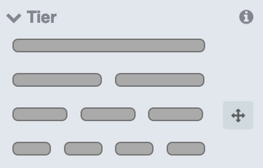
Currently tiers are simple, representing 1 to 4 locations. It is special in that it is not current distributed in the catalogue and is only represented in software, with standard set of keys. This is what it looks like in the pick list of the design tool.
Location
Locations represent a place in the world where your computing can be installed. Locations are predefined in the catalogue and only these places may be used in a design. The are typically, data centres and data halls (separate buildings in the data centre estate).
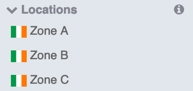
To the side are set of examples taken from the design pick list, starting with an AWS Ireland catalogue. Below is a set of three availability zones within the EU-West1 location. It is not possible to mix major locations in AWS as they don't have universal coverage of products, so each needs to be tailored. Consequently, It is just named A, B and C.
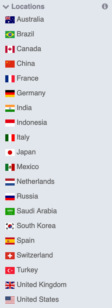
The list below is taken from the Abstract catalogue and represent a set of general country locations. They are there so one can express a global architecture easily.
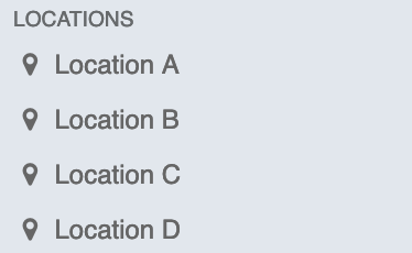
Below is a set of generic locations, for conceptual designs. Sometimes we just want to say ‘Location A’ and ‘B’, replacing them when we know more about out problem.
In addition the common data, locations also collect the following:-
Location code and sub-code - The reference the vendor uses to identify the location in machine descriptions of configuration. A sub code might be used for two part location specifier.
Logitude and latitude - For showing the location on a map.
Time zone
2-character ISO country code - Helps display flags and the like.
Captial and charge uplift - If there is a simple uplift in costs for a location, it can be specified here. For example The UK might be 1.2 times the cost of the US for everything.
Network
Networks are quite a broad category, ranging from area or mass deployment technologies, to point-to-point technologies. Predominately, at the centre of every technology is a piece of hardware with a finite location. However, there are also a contribution from software (for address discovery) and also a more abstract, multi-location set of concepts.
Currently, there are divided into four categories:-
Area Connectivity
Mass connection of many machines into a local area network (LAN) for general connectivity (typically over IP) and storage networks (SAN). We dont attempt to model any physical connection or represent the ‘real’ world such as connection diagrams. Instead, we model a logical relationship based on set membership, with a piece of real hardware in the middle.
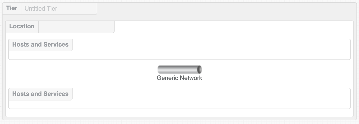
Area connectivty in a cloud environment is pretty light on details; often we just dont need to know anything other than speed. Sometimes, we dont even get to know that. Below is area network is represented in a design, looking somewhat Venn diagram-like.
It shows an unnamed tier, with an unassigned location holding a generic network, represented by a long pipe. (It can also be represented by a more traditional router or hub symbol). Above and below are zones where the hosts and platform may be dropped. They form membership of that area networking.
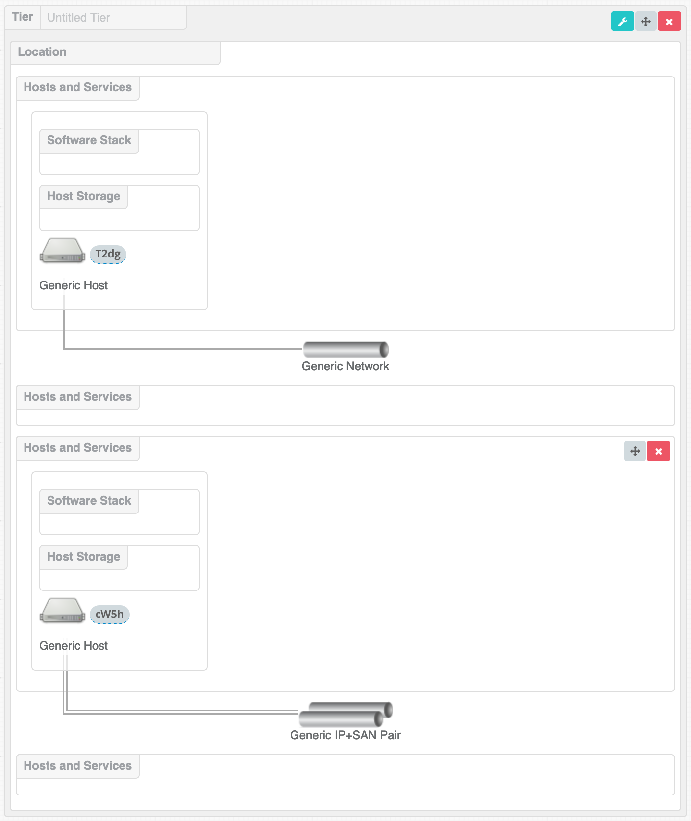
It is expected that there would be two types of network to choose from (and thus model). An IP network and an IP+SAN combined network (which has been shown as a double pipe and connections are double lines). The latter assumes that one always needs a LAN, but in addition has a set of SAN connections presented to the machine. Traditional database servers would typical of the use case for this. NAS storage devices, SAN over IP and now NVMe over fabric would (of course) just use a LAN.
The diagram below shows an IP network and a IP+SAN netowork combined, both with one generic host attached. Whilst the diagram is a set, a line repsenting a network connection helps to maintain a congnative anchor to the ‘real world’. The SAN+IP network have double lines and double pipes for emphasis.
Hosts and platforms may only be a member of one set at a time to keep diagrams simple (a design goal). If membership of more complex scenario is needed, then compose a new network type that blends the requirements. Area connectivity is still maintained, albeit with a small membership of a more specifc set of technology.
Multi-homed host connectivity is not currently supported, but may be in the future. Instead, use separate dedicated area networks of one and link them. This may, in fact, be the closest way to represent this scenario in the future.
Control Points and Point-to-Point Connectivity
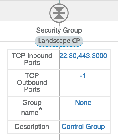
Area networks can be linked by using a control point (CP). A control point is a device (or virtual device service) that connects isolated networks (such as unrouted subnets or VLANs) and optionally performs actions on the passing traffic. For exmaple, a firewall, which passes some packets and drops others.
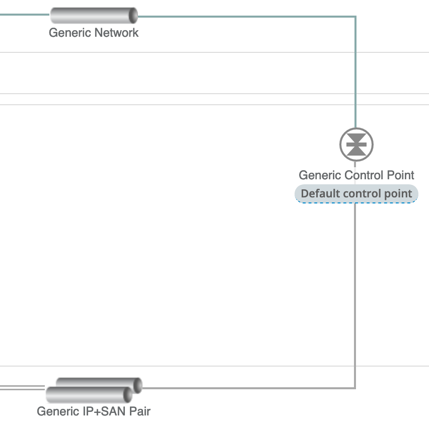
The diagram below shows how the component is represented in a design.
The two area networks (the pipes In the diagram) are connected to a generic control point (with a double diode style symbol).
If the CP was a firewall, it would represent linking the two networks with a firewall.
A specific case and used very commonly, is the representation of a security groups or internet gateways in cloud environments that host data on the internet.
Network Equipment
These network devices can be placed in a location and a tier, but do not participate in area networking, so they are not like a regular host or service. Once located, there needs to be point-to-point connections into other devices or an area network. These can be one-to-many, many-to-one or many-to-many.
An example is a load balancer, which would be a one to many connection.
Service Discovery
Hosts are given names in the design and this is used to reach each other within a network and potentially the outside world. However, external advertising of a service is also necessary and this is done with a ‘naming’ flag dragged on to the host and will be picked up by the naming service when compiled.
Currently, the naming flag is implemented to be dragged on to the software stack of a suitable host.
Catalogue Data Held
In addition to core data, for following is also held:-
Network types: IP and SAN currently
A script to implement the component using an orchestration language, such as Ansible (see later)
Inbound and outbound charges. It is common for cloud providers to charge based on the transit of data at their boundary. We can represent this at a system level by putting a tollgate on the boundary gateway and adding the per-GB charge into the design cost.
Host
A host in an execution platform that is able to run software.
There are several types of hosts, although the catalogue does not yet require them to be distinguished.
Phyiscal machines
Virtual machines
Containers or pod platforms
Serverless platforms for function as a service or lambda
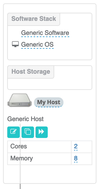
Hosts are effectively a contract, for how to combine software, storage and configuration to provide functionality. They are represented in Fabric as follows:-
In the centre, an icon of a physical server and the name in an oval like a cartouche. Below that is a table with parameters that change how the host is configured and is set up in the catalogue. (See the description of configuration tables later.) Above are drop areas for storage components and a stack of software components.
When you define the host, you get to specifiy the icon to be used, the provider code for the component (an SKU) and the configuration you need to collect to adapt the server. Storage suitable for hosts is dropped in, configured and mapped to directory mount points.
Finally, the software stack is a list of software, starting from the bottom and reading upwards. The lowest level is the operating system, a specific type of software (see below). Each line will be installed in order going up the stack; typically the application and install script will be the last to complete.
Software
Software components cover the whole range of how code can be used and deployed on a host. It is subdivided into six types:-
Operating system - Generally provided by the cloud provider, or possibly created by your engineering group on top of the basic cloud image.
System software - Often packaged by the OS vendor in an RPM or APT. The index can be created by a script from the standard distributions.
Application package - Similar to the system software, execept generated locally. If you include code in the catalogue, it will tend to be libraries or things with a relativelty long shelf life, as it will need to be supported for a relatively long time. As each package has a lifetime attached, it forms part of the contract with the user for software dependability.
Proxy - Rather than software itself, it is a method defined in the catalogue, such as a Git clone, file transfer/copy or a Docker pull. More information is provided as configuration parameters, but the actual snapshot of code happens at deploy-time. This makes it very suitable for customer written code, in addition to additional convenience methods.
Container - Another type of application or system package. Proposed not yet implemented.
Installation - An execution method, to be run when the previous component in the stack has completed installation, but before the next one. The method runs a shell script on the destination machine, and is designed to complement the installation steps or finalise it. However, it could completely replace the stack and catalogue model; what ever is the most convenient.
As shown in the host section, the software is placed in a stack, which orders the seqence of installation. Software can be reordered as necessary. Operating systems are always run first and only one can be used.
In additon to the core data, software components hold the following:-
The user to install the software
A flag to patch the software to the laest version, if supported by the packaging method
A script to install the software, passed to the orchestration method
The software type
Service
A network attached shared resource that provides a service to the desiogned system and is able to hold state with optional storage for the application.
It is an abstract set of functionality with a defined interface only and a set of deploy-time parameters. Conventionally, the relationship is request-reply from the host, but other styles of communication are possible due to the automated design-deploy process holding a graph of association.
Services can have a list of storage assigned to it that will be private to the application and can be either NAS, SAN or host types. All services have an owner, support, a network attachment and a single location, even if the multiple servers or locations are used in the implementation. Each service type may have configuration parameters that are exposed to the infrastructure provider at deployment
Storage
Data storage which can be one of three types:
SAN - Storage area network for block storage devices such as SAN arrays
NAS - Network attached storage for file storage
Host storage - Block storage that is presented to hosts so that they can incorporate it into the operating systems.
Each storage component may have configuration parameters that are exposed to the infrastructure provider at deployment, such as filesystem name
Cluster
Proposed
Blueprint
A predefined set of components that form a functional tier inside a design. Eg a complex database configuration. Blueprints are made from successful designs that are narrowly scoped to be a library, rather than a complete solution.
Designs that form blueprints should not use named resources, so that they may act as library material.
Configuration
Many catalogue types need additional information from designers to configure the component correctly. For example, the size of storage, where it should be mounted or how much memory should be assigned.
In the catalogue definition is a table that drives the collection of the data in the design. An example for a networking component is below:-
The values are:-
Name appears in the design
ID is the token used in an associated script
Description is a popover used with the config
A type field offers a limited range of values: str, int
Default is the value to use if no input is given, and finally
Required is a flag ‘y’ or ‘n’ to make the compiler that a value has been put in.
During design process, the configuration parameters appear in a table adjacent to the component being positioned (see below).
Orchestration
Fabric compiles designs into an orchestration language in order to deploy with a cloud provider. Different languages or methods exist. Ansible is the current primary method, but we should also consider the generation of a ‘printed paper’ set of plans.
When a new catalogue is defined, there are two settings: the orchestration system (such as Ansible) and the infrastructure provider (such as amazon or Azure).
The sections below show how each is rendered.
Component Scripts
Many catalogue components use a script and configuration items to encode a fragment when then is placed into the overalll output. The configuration definiton and collection is described above. The values from these are presented back to the scripts using the ID token provided by the definition by using a ‘$’ sigil it introduce it.
By using script fragments, it is possible to become more flexible by using alternative approaches that may be abelalable. For example, Ansible has a shell and a command module that achieve similar things in slightly dfifferent weays. Moving it to the catalogue definiton rather than hard coded in the compiler allows more flexibility.
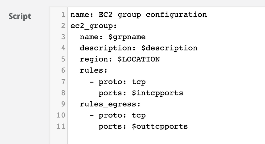
Below is an example of a security group being set up for AWS in Ansible:-
It shows coniguration variables being used: $grpname, $description, $intcpports, $outtcpports. It also shows the compiler environment value $LOCATION being used. By convention these are in captials to distinguish from configuration values. Different component will have the advantage of different envionrment variables.
Ansible
The current default orchestration language for System Garden is Ansible. The back end generators produce a framework that works for the provider and orchestration, using component data such as Skew and other information. In addition the component scripts are used to add to the backend generation.
The Ansible is sent directly to the provider and the deployment progress is tracked.
Print
Catalogues have a number of targets that are possible for their back ends. Ansible is an example of an automated system. Another one, far more manual, is just to print out the instructions on to paper (or PDF or an iPad). This can then be followed by data centre engineers who are able to build physical assets.
This would entail a separate catalogue that prints as its target.
Others
Other back ends are under development, including Terraform. Contact System Garden for more information.
Pseudo Catalogues
Abstract
Not all designs have to use real components from cloud providers.
You may not wish to be committed to a particular size or a certain vendor. Instead, a special catalogue exists called Abstract. This contains only generic components (see below) and a number of others to enable designs to be expressed without fixing on a platform.
Abstract catalogues can not be deployed as there is no real product behind it, and the compilers will prevent this. It is used for expressing ideas only.
It is possible, however, to use Abstract and Generic components to build actual systems. It would be necessary to convert the Abstract catalogue to a cloud one. Once a rough conversation has taken place (by changing the catalogue in the design tool), the design can be honed by individual customisations of the components.
Generic
Every catalogue has the same set of generic components, shared with each other and the Abstract catalogue. This allows for certain items to remain unresolved even if a cloud vendor is chosen.
It also allows designs to be converted from one provider to another. Real parts from one catalogue are turned into generic components and the catalogue is changed. The generic parts remain intact during transfer. Then the components can be migrated to their destinations.
Future Expansion
A rule base to stop incompatibilities. ie linux+windows os. or linux and windows app
